In this essay, we demonstrate a stress analysis of a plate with a central single circular hole subjected to axial loads. The aim of this study is to determine stress distribution around the hole area. After installing simulation software WELSIM v1.0, you can conduct this study on your own computer as well, the geometry file in this example is provided in the installation package with file name “planeWithCornerHole3d.step”.
Problem description
A plate with a central single circular hole is pulled on both left and right sides, the dimension of structure is shown in the figure below. Material: structural steel with Young’s modulus E=200 GPa, Poisson’s ratio u=0.33. Pulling pressure: P = 100 MPa Dimension of plate: 100 x 100 x 5
Reminder: WELSIM is dimensionless, the user ensures the consistency of units.
Keynotes: 1) At preliminary observation, we know it is a plane-stress problem. While we use 3D solid element for this example instead of applying 2D plane-stress assumption. 2) Due to the symmetric geometry and loads, we use only a quarter of geometry with symmetry assumption.

Start WELSIM
Two methods to start WELSIM application, user can choose either one of them. 1) double click the desktop shortcut icon of “WELSIM v1.0” 2) Select from Windows “Start” menu: [Start] → [All Programs] ->[WELSIM] ->[WELSIM v1.0]
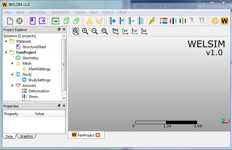
After starting WELSIM, the main window shows up. Clicking the “New project” toolbar button, we will create a new FEM project with essential objects in the tree window if the application has been activated with license key. The main window is shown as followed:
Import Geometry
Clicking the ”Import” toolbar button, we can read a *.step format CAD file into WELSIM. In this example, we import geometry file named “plateWithCornerHole3d.step”, which is in your installation/data folder.
Mesh
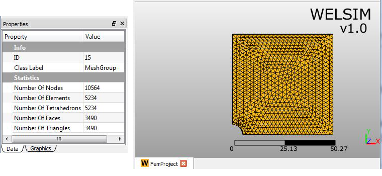
WELSIM v1.0 uses fully automatic meshing scheme, user can control the mesh density and element type. In this example, we set “Maximum Size” property to 2, and other properties remain as the default values. Clicking the meshing toolbar button, we generate Tet10-based mesh. The statistics data such as number of nodes and elements can be reviewed at properties of Mesh Group object:
Impose boundary conditions
Now we impose three boundary conditions, one pressure acts as an external load, two displacement constraints denote symmetry:
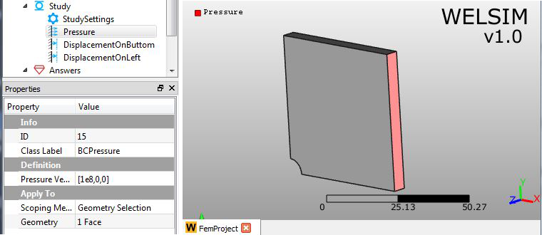
1) Clicking “Add Pressure” toolbar button, we insert a new “Pressure” object node in the “Study” branch. Then we can define the imposed area and pressure values at properties window. In this example, we impose the pressure on the right side of the body with the magnitude of 1e8 on the X direction.
2) Clicking “Add Displacement” toolbar button, we insert a new “Displacement” object. Right mouse button clicking on the object node, we can change the object name, here we rename it to “DisplacementOnButtom”. Then we scope the bottom face and key in displacement value 0 for the Y component.
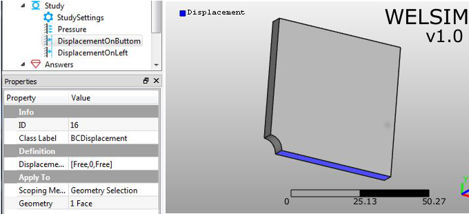
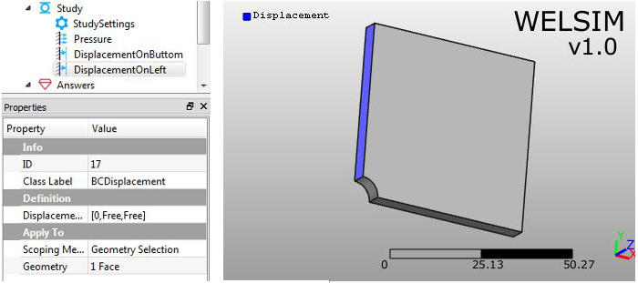
3) We add another “Displacement” object and rename it to “DisplacementOnLeft”. Then we scope the left face and input displacement value 0 for the Z component.
Solve
When all conditions are properly defined, simply clicking the “Compute” toolbar button, we start to solve the model. The solving should be completed in seconds with mainstream hardware.
Evaluate Results
WELSIM v1.0 supports displacement, stress, and strain results. More details can be found here. Clicking “Evaluate all results” or “Evaluate result” toolbar button, we can evaluate and analyze solutions. Here are major results we inspect:
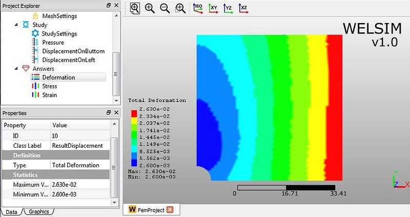
1) Total Deformation
2) von-Mises stress

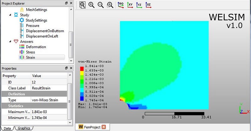
3) von-Mises strain
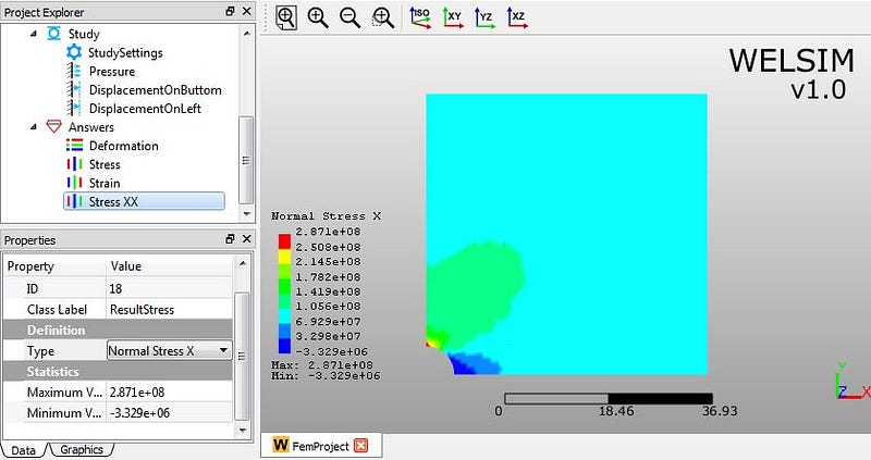
4) Clicking the “Create stress result” toolbar button, we add a new stress result object node into the “Answers” branch, and rename it to “Stress XX” to differentiate from other stresses. In the property window, we set the “Type” to “Normal Stress X” through the drop-down list. Then evaluating this result, we have the normal stress distribution along the X direction:
Conclusion
When we know the deformation and stress results, the analysis on a plate with a central circular hole is almost done. We get the maximum von-Mises stress value 2.768E8, which occurs on the upper and lower bounds of a circular hole. Combining the yield stress of the material, we will know whether this plate design is appropriate or not.
What type of analysis would you see in the next essay? Leave your messages and let us know.