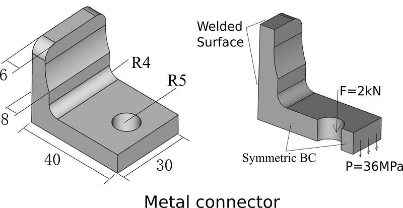
The metal connector is widely applied in the mechanical engineering. As shown in the figure below, a typical connector has elbow shape, the back surface is welded onto another bulk structure, a circular hole, allocated at the extended area, can be connected with bolts. The dimension and working loads are shown as well in the figure. Now we need to know the deformation and stress distribution, which is essential to understand and optimize such part, for example, to reduce the stress concentration in the critical area.
This study can be conducted using simulation software WELSIM. If you have installed WELSIM v1.0, a CAD file called “standHalf3d, step” is included in your “data” folder.
Problem Description
Material: Youngs’ modulus: E = 200 GPa, Poisson’s ratio u = 0.33
Loads: 1) hole area stands a vertically downward force F =2 kN. 2) exterior surface stands a shear pressure P = 36 MPa.
Constraint: The back surface of the connector is fully constrained to denote welding.
Reminder: WELSIM is dimensionless, user ensures the consistency of units.
Keynotes:
Due to the symmetric geometry and loads, we use only a half part of geometry for the following analysis. The displacement boundary conditions will be imposed on the plane of symmetry.
Start WELSIM
There are two methods in starting WELSIM application, user can choose either one of them.
1) Double click the desktop shortcut icon of “WELSIM v1.0”
2) Select from Windows “Start” menu: [Start] → [All Programs] ->[WELSIM] ->[WELSIM v1.0]
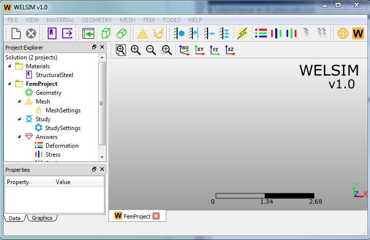
After starting WELSIM, the main window shows up. Clicking the “New project” toolbar button, we create a new FEM project with essential objects in the tree window. The main window is shown as followed:
Define Material
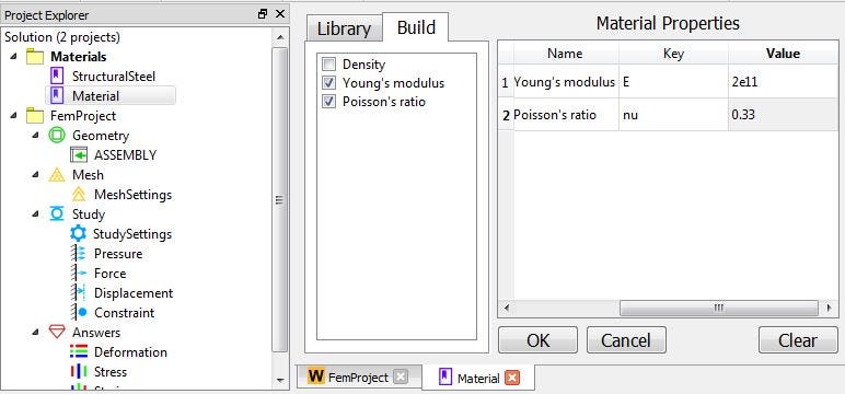
Although the application provides a predefined “Structural Steel” material, we create a new material here to better know the material building process. Clicking the toolbar button “Add Material”, we insert a new material object to the material project. Double or RMB clicking on the newly added material, we open material editing panel. In this analysis, we define “Young’s modulus” and “Poisson’s ratio” to 2e11 and 0.3, respectively. Clicking “OK” button, we save it to the database. Is it very easy?
Import Geometry
Clicking the ”Import” toolbar button, we read a *.step format CAD file into WELSIM. In this example, we import “standHalf3d.step”, which is in your installation/data folder.
Mesh
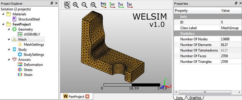
WELSIM v1.0 use fully automatic meshing scheme, the user can control the mesh density and element type between Tet10 and Tet4. In this example, we set “Maximum Size” property to 2, and other properties remain the default value. Clicking the meshing toolbar button, we generate Tet10-based mesh. The statistics data such as number of nodes and elements can be reviewed at properties of Mesh Group object:
Impose boundary conditions
Now we impose four boundary conditions, one pressure acts as an external load, one concentrated force on the hole surface, one full constraint on the back side, and one displacement constraint to represent symmetry.
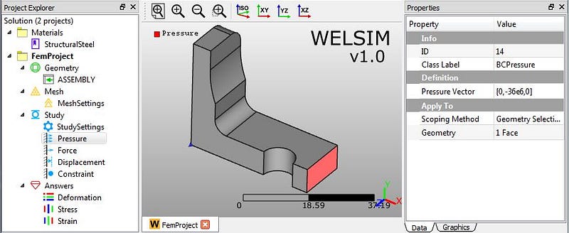
1) Clicking “Add Pressure” toolbar button, we insert a new “Pressure” object node in the “Study” branch. Then you can define the imposed area and pressure magnitudes at properties window. In this example, we impose the pressure -3.7e7 on the Y direction on the exterior surface.
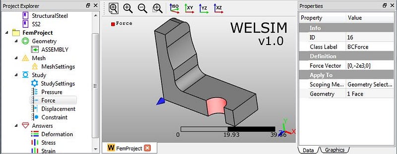
2) Clicking “Add Force” toolbar button, we insert a new “Force” object node. Then we impose this concentrated force on the circular surface with a magnitude of -2e3 on Y direction.
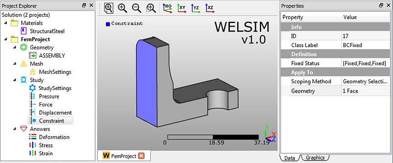
3) Clicking “Add Constraint” toolbar button, we insert a new “Constraint” object node. Then we impose this constraint on the back surface of connector.
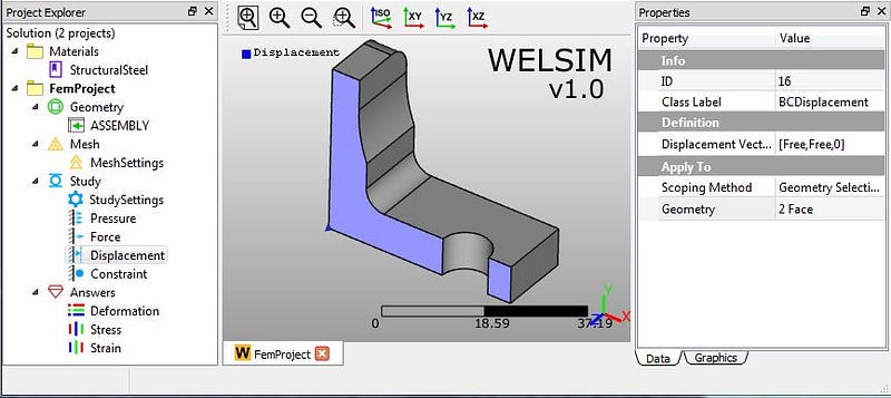
4) Clicking “Add Displacement” toolbar button , we insert a new “Displacement” object. Then we scope it to the plane of symmetry, and define displacement on Z direction is 0.
Solve
Simply clicking the “Compute” toolbar button, we start to solve the model. The solving should be done quickly.
Evaluate Results
WELSIM v1.0 supports displacement, stress, and strain results. Each type of result supports different directions or components. More details can be found here. Clicking toolbar button ”Evaluate result” or double clicking on result object nodes, we evaluate and analyze solutions. Here are major results we are interested:
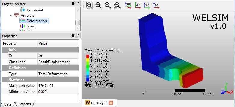
1) Total Deformation
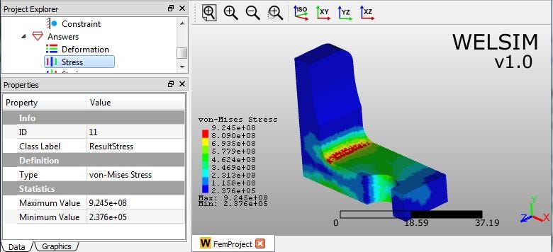
2) von-Mises stress
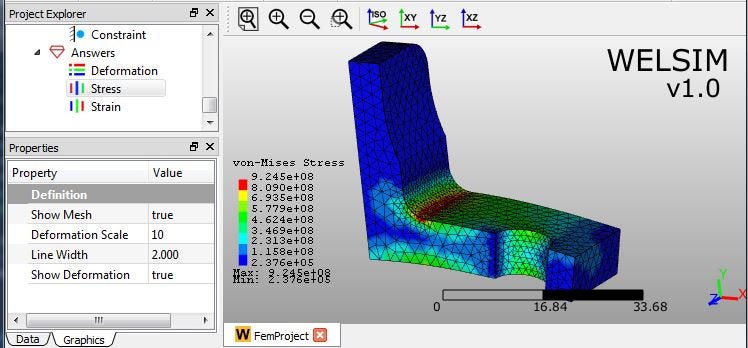
3) von-Mises stress with mesh and deformed shape
Conclusion
Once we know the deformation and stress results, the analysis of a metal connector is almost done. We obtain the maximum von-Mises stress 9.245e8, which occurs at the elbow corner. Combining the yield stress of the material, we know if this connector is well designed, and how to optimize it.
What type of analysis would you see in the next example? Please leave the message and let us know.