Plate structure with holes is widely applied in engineering practices. The reason making holes on the plate could vary, some for installing bolts and other connectors, and others for reducing weight without mainly affecting mechanical properties. Today we use finite element based simulation software WELSIM to analyze the plate subjected to tensile loading and verify the accuracy of the numerical solutions.
The geometric properties and loads of the plate are shown below. A rectangular plate structure with a fixed left side and a tensile pressure on the right side. There is a circular hole in the center of the plate.
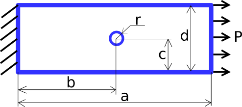
To better simulate the conditions and verify the correctness of the values, the following gives a specific structure size, force size, and material properties:
Here the Poisson’s ratio is set to zero so that the force in one direction will not affect the deformation and stress in other directions. The purpose of doing this is to compare the numerical results with the theoretical results.
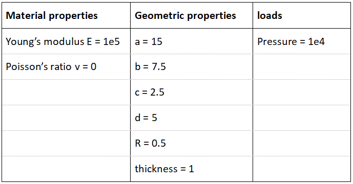
Open the software WELSIM below and set the material parameters. Create a new material node and add two properties of elastic modulus and Poisson’s ratio as shown in the figure:
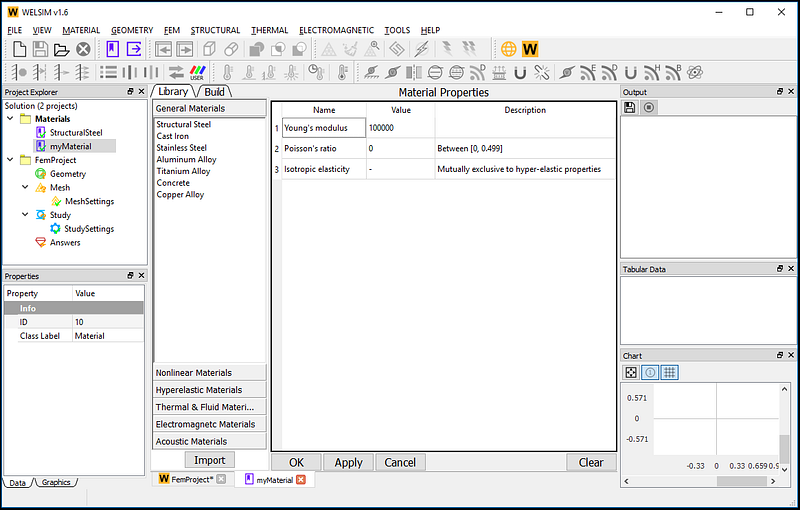
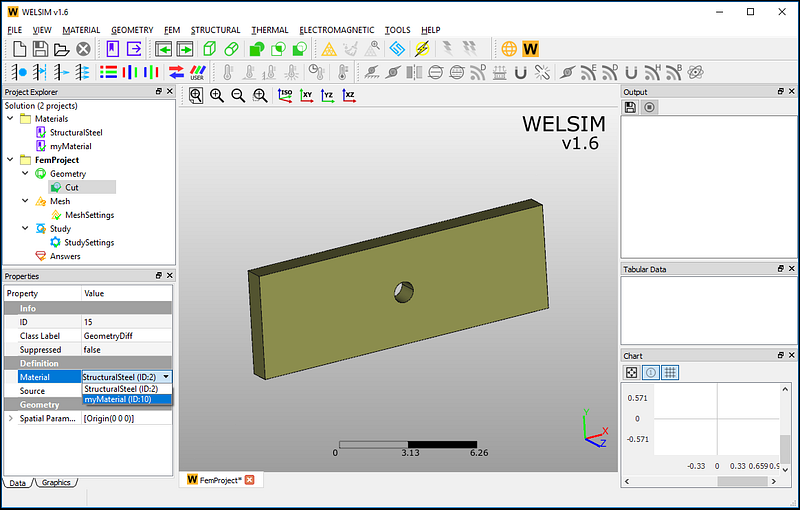
Since it is a plate structure, we can build the plate with holes by creating a plate and a cylinder and then using Boolean operations:
And give the newly created plate the material we just defined, as shown:
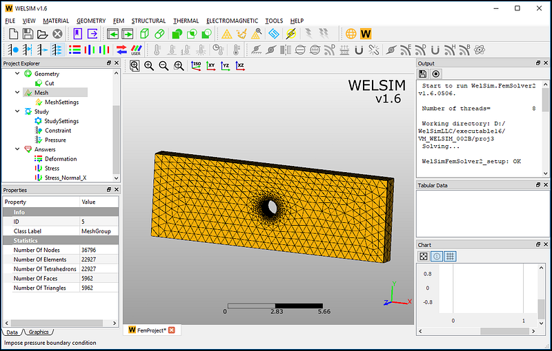
The next step is defining the mesh parameter and generating the grids. Since the stress around the hole is relatively concentrated, we set a relatively dense mesh around the hole. The meshed elements and nodes are given as follows. A total of 36796 nodes and 22927 tetrahedral elements are generated.
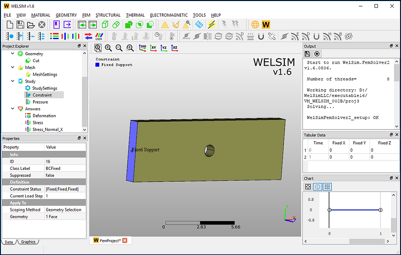
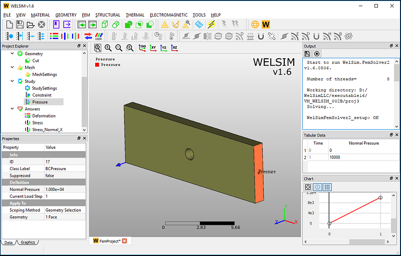
Next, add two boundary conditions, one displacement constraint is applied on the left surface, and one tensile pressure with the magnitude of 1e4 is imposed on the right surface.
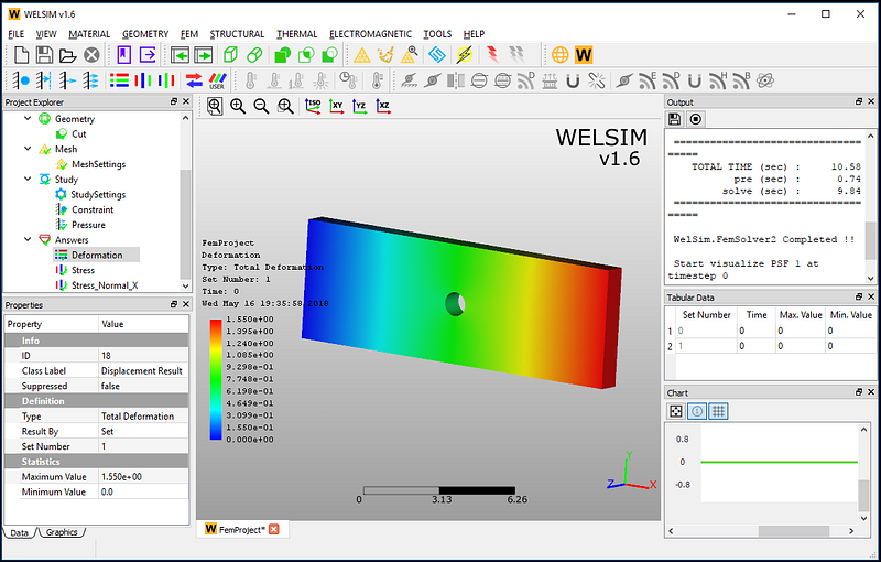
Now all analysis settings are defined. Click the Solve button, and the results will be available soon. After the calculation, add total displacement, and X normal stress result objects. Evaluate the result objects. The resulting contour looks like this:
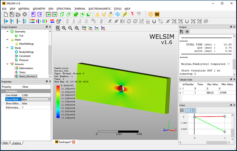
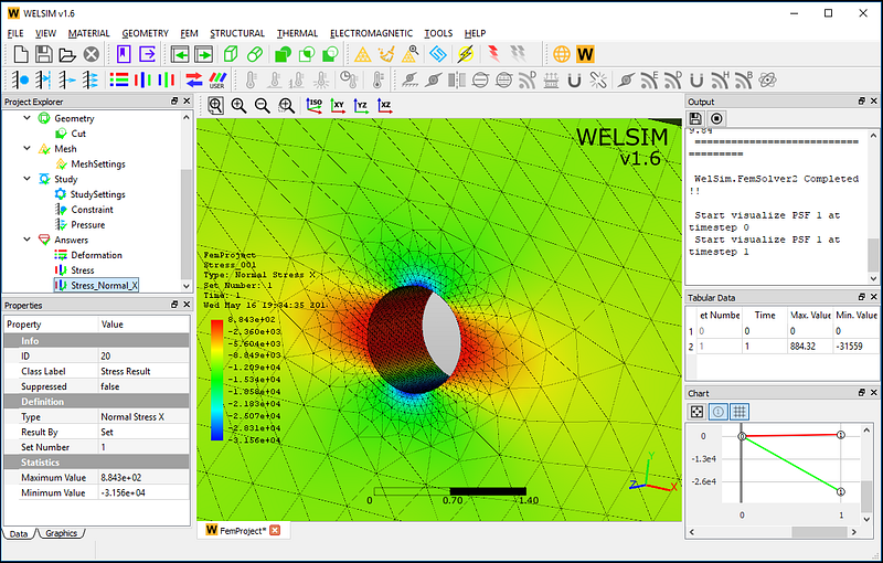
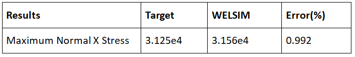
Next, we verify the results of X normal stress. The numerical results are very close to the theoretical values.
This simulation example is saved in the WELSIM software installation directory. Users can directly open the file named VM_WELSIM_002B.wsdb for calculation and verification.