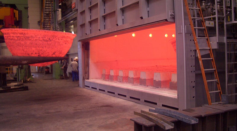
The furnace is one of the most commonly used equipment in the industry. The gas burned in the furnace combustion chamber is discharged through the channel of the wall. The furnace wall isolates the flame, high-temperature gas and various heat surface components from the outside. As an essential part of the furnace body, the furnace wall can not only prevent the heat loss in the furnace, but also prevent the flame and gas from being blown out to ensure the safety and sanitation of the operating personnel.
To be able to perform the functions, the furnace wall should have excellent thermal insulation, proper sealing, and sufficient heat resistance. The above requirements of the furnace wall not only require right refractory materials, but also the design and thickness of the furnace wall are significant. In this article, we come to understand the design of the furnace wall through finite element simulation technology, and intuitively understand the temperature distribution of the furnace wall.
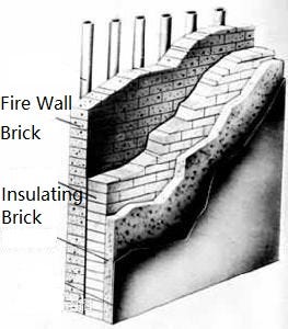
To better meet the requirements of thermodynamics and structures, the furnace wall is usually designed into several layers. The inner layer is a firebrick wall, and the outer layer is a thermal insulation wall. The layers are made of different refractory materials. The schematic view is as follows:
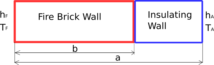
To reduce the analysis time, we focus on a small part of the furnace wall section for analysis. The results should provide the same insights as the analysis of the entire wall. A diagram of the furnace wall is as follows. Here, it consists of two different materials, one is refractory brick, and the other is insulation brick. Both sides have different thermal convection parameters.
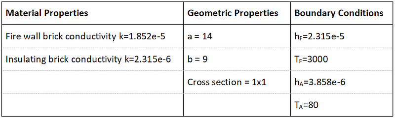
To better model composite wall and verify the numerical solutions, the following gives specific material properties, geometric properties, convection coefficients, and ambient temperature:
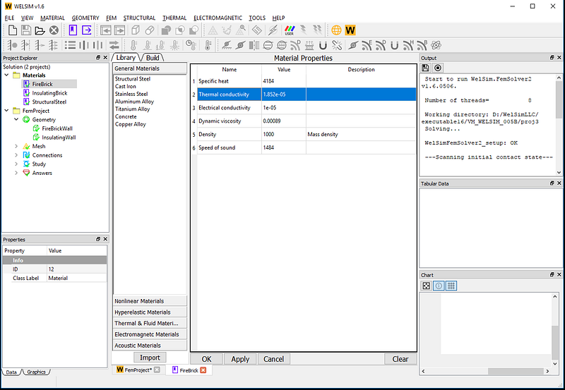
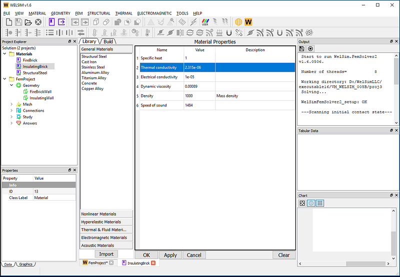
Now, open the simulation software WELSIM. Create two new material objects. Since it is a steady-state thermal analysis, we add and define the thermal conductivity coefficients as shown in the figure:
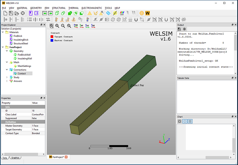
Next, add two brick bodies, set the size of the geometry. Add a contact object to combine two bricks to build a composite wall. The geometry is shown in the figure below:
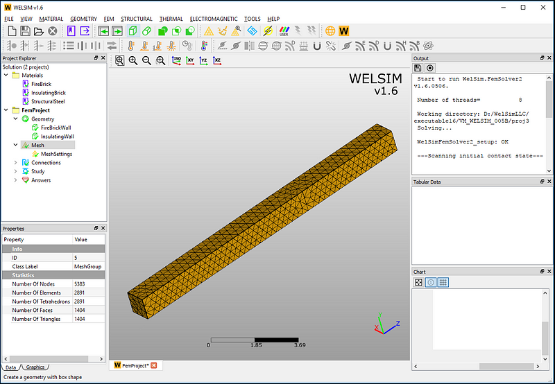
Next, we define the finite element mesh. Just set the unit size and click on the meshing button. A group of high-order tetrahedral elements will soon be generated. The mesh is composed of 5383 nodes and 2891 elements.
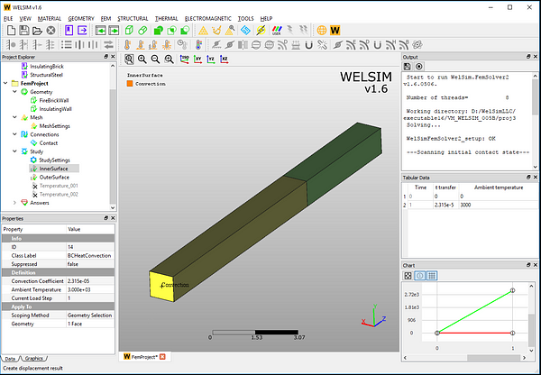
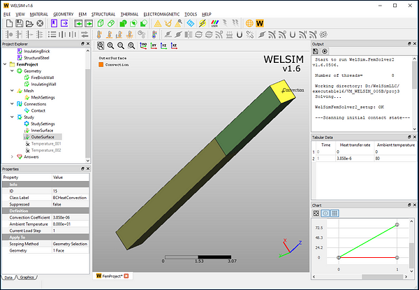
Next, add two thermal convection boundary conditions respectively. One is used to simulate the inner surface at the furnace end and another to simulate the outer surface s of the insulation wall.
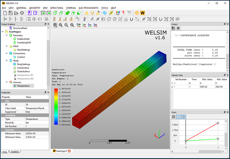
All settings have all been completed. Click the Solve button, and the results will be available soon. After the calculation is finished, add a temperature result node and display the temperature distribution through the wall. The temperature contour looks like this:
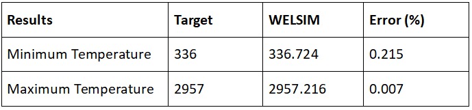
Next, we verify the maximum and minimum temperatures. It shows that the finite element numerical results are very close to the theoretical ones.
With this thermal analysis, our engineering staff can quickly understand the heat distribution of the wall and whether the wall thickness meets the work requirements. Here we use WELSIM to analyze a two-layer furnace wall. In practical projects, the analysis methods for the three-layer and multiple-wall furnace walls are very similar.
This thermal verification example is archived in the WELSIM installation directory. Users can directly open the file named VM_WELSIM_005B.wsdb for calculation and verification.