The structural analysis of the assembly using WELSIM is straightforward. The main steps are: (1) define the materials; (2) create geometries and assign materials; (3) define mesh settings, and generate grids; (4) define analysis settings and impose boundary conditions; (5) define solver settings and compute; (6) evaluate and display results.
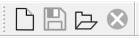
Create a new FEM project or read an existing saved project. After opening the WELSIM software, you can click the New or Open button from the toolbar as shown:
If it is a new project, the system will initialize some default objects on the tree. Users can add more conditions and objects based on the current tree.
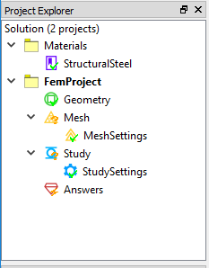
If you open a saved file, a more completed tree structure could be generated (depending on the contents of the opened file).
Each tree object has an indicator icon, and the meaning is as follows:
- Green checkmark: The object setting is complete and correct.
- Orange question mark: object settings are incomplete or not updated. Users need to fill data or update object.
- Red exclamation: There is a conflict between the object and other settings. Users need to modify the settings or suppress/remove the object.
- Black cross: The object is suppressed and not participated in the entire analysis. Users can change the suppression state by setting “Suppress/Unsuppress”.
1 Define the material
Firstly, we define the materials and properties that will be used in the analysis. Users can add a new material object to introduce a new material definition. In the newly created project, a material object named “Structural Steel” has been added by default. If you need other materials, click the New Material button from the toolbar.

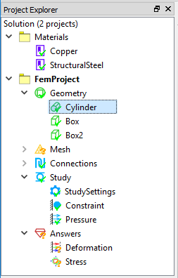
After clicking the button, a new material object is added to the tree. However, the content is empty, and the orange question mark indicates that the material object is not fully defined. Double-click the material node, or right-click and select “Edit” to add material properties and parameters.
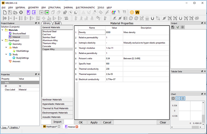
Material properties can be added directly through the system’s predefined materials. Users can also add properties one by one entry through the “Build” tab. Here we directly select the system predefined “Copper Alloy” from the “Library” tab, the content is as follows:
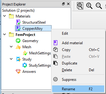
After clicking OK, the material editing window will automatically close, and you will find that the state of the material object has been updated. To better identify the material in the following analysis, we rename the object to “Copper Alloy”.
2. Define geometry and assign material
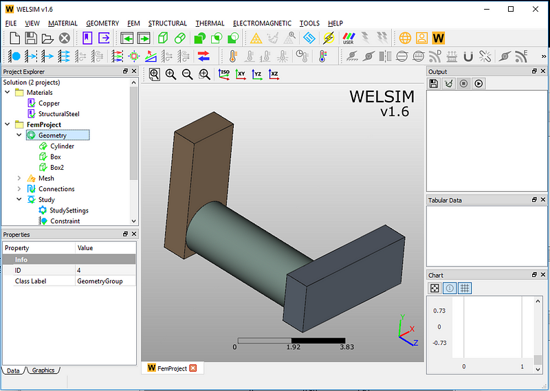
Next, we begin to create or import geometries. WELSIM supports the creation of simple geometries such as cylinders and blocks. Users can also import STEP model files generated by CAD software. Here we define an assembly consisting of one cylinder and two bricks as follows:
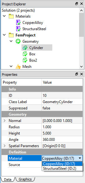
Now we assign the “Copper Alloy” material to the cylinder structure. In the properties window of the cylinder, click the Material drop-down menu and select “Copper Alloy”. Other geometries maintain the default structural steel material.
3. Define mesh settings, and generate grids
WELSIM supports automatic meshing and can generate Tet10 (default) or Tet4 elements. Users can define the quality or density of the mesh in the properties of the MeshSettings object. The mesh setting parameters are as follows:
- Maximum Size: The maximum size of the generated element. The smaller the value is, the denser the mesh is.
- Quadratic: Generates second-order (Tet10) or first-order (Tet4) tetrahedra elements. The default value is True (Tet10).
- Mesh Density: Generates elements with different mesh densities within the range defined by the Maximum Size. There are six options, Very Coarse, Coarse, Regular, Fine, Very Fine, and User-Defined.
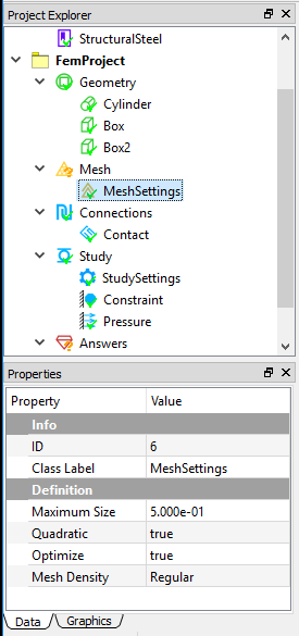
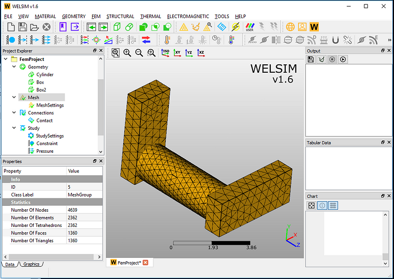
Here we set the maximum value of the element to 0.5, and keep other properties by default. Just click on the Meshing button.

The program automatically meshes the domain. As can be seen from the Mesh’s properties window, 4639 nodes and 2362 tetrahedral elements are generated.
In addition to mesh generation, WELSIM also provides mesh cleaning and inspection features:
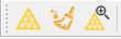
Users can click the mesh check button. The system will automatically check the quality of the mesh, and output the mesh information in the Output window.
4. Define analysis settings and impose boundary conditions
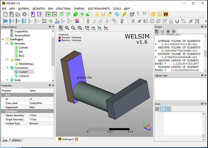
Next, we define the contact pair for this assembly. Here there are three parts, which need two contact pairs to assemble. Click the contact object button from the toolbar and add two contact pair objects in the tree structure.
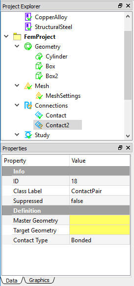
There are three Contact Types provided: Bonded, Frictionless, and Frictional. In this analysis, we use the default Bonded contact to connect the parts. Then you only need to define the Master Geometry and Target Geometry by scoping the specific surface from the graphics window. You can hold down the Ctrl key to select multiple surfaces.
After selecting the Target and Master surfaces, the bonded contact definition is complete. One of the defined contact pairs is shown below.
Next, we impose the boundary conditions. Since it is a static analysis, users can just use the default analysis settings. In the static analysis, WELSIM currently supports four kinds of boundary conditions: Constraint, Displacement, Force, and Pressure.
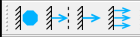
Here we add two boundary conditions: constraint and pressure. In the constraint boundary, select a surface in the geometry window as follows:
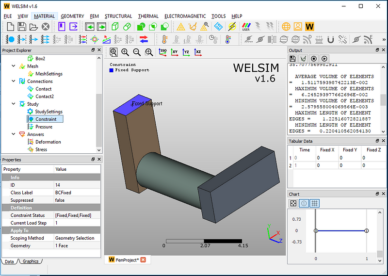
For pressure boundary conditions, choose a surface from the other end of the assembly and set pressure value to 1e6.
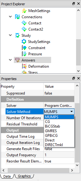
5. Define solver settings and compute
In the solution settings, the system provides different solvers as shown in the figure. Here we use the default MUMPS solver, which is a direct solver.
Next, click the Solve button

to complete the calculation.
Evaluate and display results
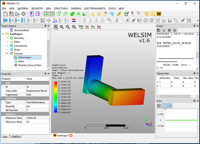
When the Output window prompts the solution, you can evaluate and view the results. At present, the static structural analysis provides four types of results, which are deformation, stress, strain, and reaction force.
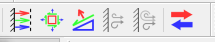
Click on Deformation, Stress, and Reaction Force button from the toolbar respectively to add these results to the tree. Click the Evaluate button,

double-click, or right-click on each result object to display.
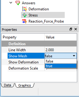
If you want to display the mesh, you can click on the Graphics tab and set the Show Mesh property to True to see the mesh presented together with the resulting contour.
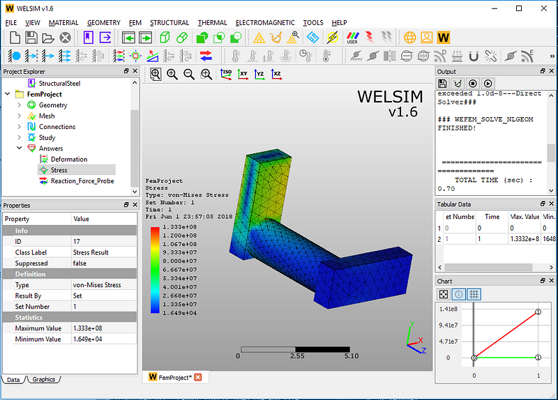
The von-Mises stress result is shown below. Users can identify if the maximum stress at a critical location exceeds the yield stress of the material. And optimize the product designs.
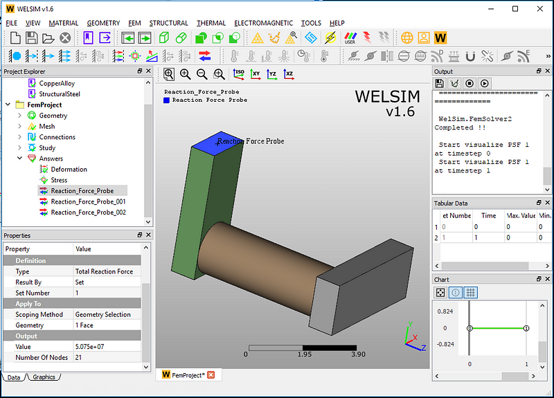
The reaction force at the fixed support is 5.075e7.
Well, the static analysis of an assembly is complete. Is it easy? Send us an email or leave a message with any questions or comments.