There are various types rotating machinery in industrial practices, such as fans, compressors, pumps, centrifuges, steam turbines, etc. Due to the relatively high rotation speed, the centrifugal force generated by its rotation is essential. When performing finite element analysis on a rotating machine, the inertial centrifugal force generated by the rotation has a significant influence on the static and dynamic characteristics of the body. This article shows how centrifugal force (rotational velocity) is implemented in WELSIM.
1. Rotational machinery blade
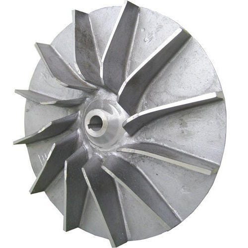
This is a machined and polished centrifugal rotating mechanical blade. The blades are welded on the disc, and the connection has been polished. The hole through the middle is used to link the shaft. Generally, this is used to connect drivers, like motors or turbines.
2. Geometric model
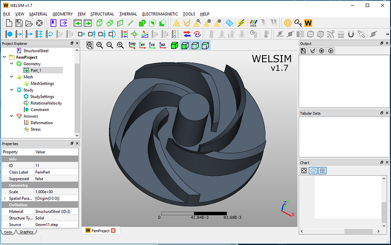
We set up a similar structure in a CAD software and imported the STEP format file into WELSIM to get the following model.
3. Meshing
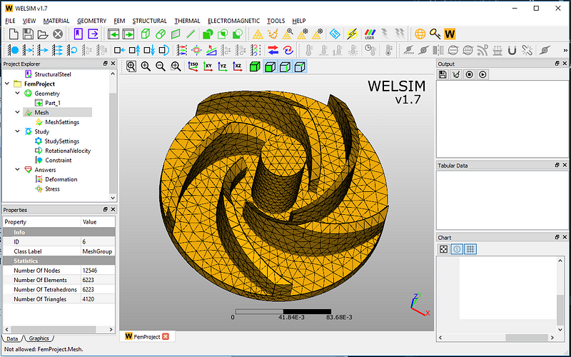
Here, we use the tet10 elements and automatic mesh generation. A total of 12546 nodes, 6223 tetrahedral elements are generated.
4. Boundary conditions and loads
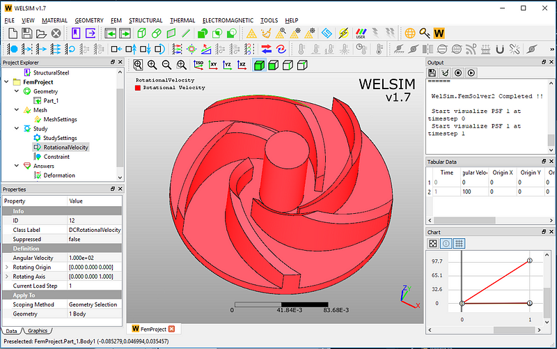
WELSIM not only provides the commonly used boundary conditions, but also supports angular velocity physical force to represent the centrifugal force.
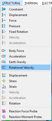
Applying a rotational velocity to the structure essentially imposes a centrifugal force on the bodies. The formula gives F = mrw², where w is the rotational velocity, r is the distance between any point in the structure to the axis of rotation. Therefore, to completely define the centrifugal force, both rotational velocity and the position of the axis must be set.
Here, the angular velocity is declared as 100 rad/s, with the blade shaft as the rotational axis.
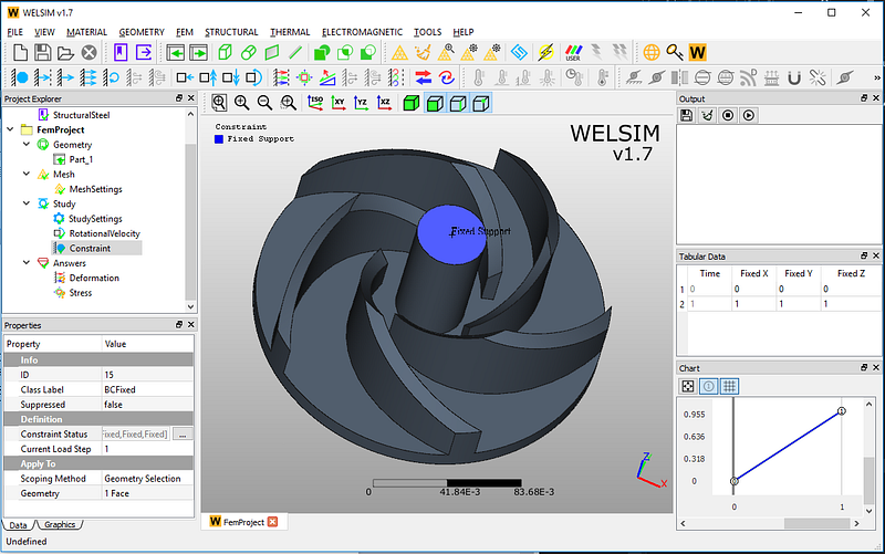
Fix the fan blade shaft.
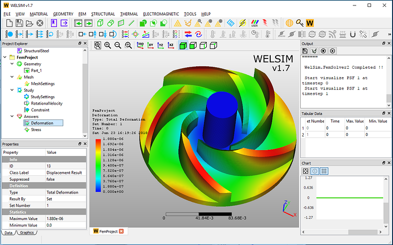
5. Results and assessment
The results of the finite element analysis of centrifugal impeller are given below. The maximum value of the total deformation is 1.880e-6, which indicates that the deformation of the structure is minimal under the current rotation velocity, material, and design.
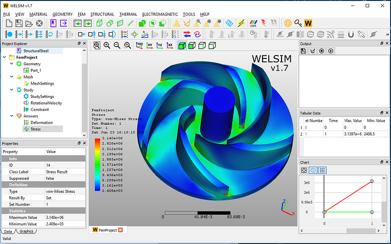
The von-Mises stress result is shown here, with the maximum value being 3.140e6. Also, this magnitude is within the allowable stress of the steel material. WELSIM displays the stress concentration located at the welding head and tail of the blade. So, in the design and manufacturing stage, these areas can be optimized and improved.
Note: The rotational velocity is a new feature introduced in WELSIM v1.7.