The STL file format (stereolithography) is an interface protocol developed by 3D SYSTEMS in 1988. It is a 3D graphics file format for rapid prototyping technology. The STL file consists of the definition of multiple triangle patches. The definition of each triangle patch includes the three-dimensional coordinates of each fixed point of the triangle and the normal vector of the triangle patch. Because its file format is straightforward, STL format is widely applied. Almost all 3D printers on the market produce prints by recognizing the STL model.
In the recently released WELSIM v1.8 version, the STL file can be read and displayed. The user can also mesh the imported STL model and save the output as a mesh file. Let’s take a look at how to use these features.
Open the WELSIM software, create a new FEM Project, and select Import Geometry from the menu bar or toolbar. The following dialog will pop up.
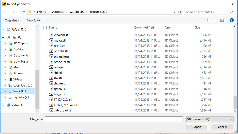
Here we select an STL file that containing an apple geometry, click Open.
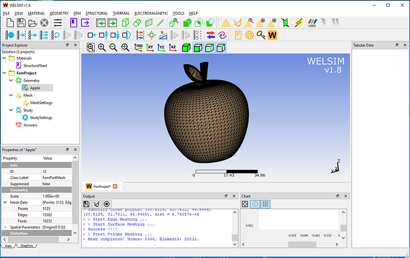
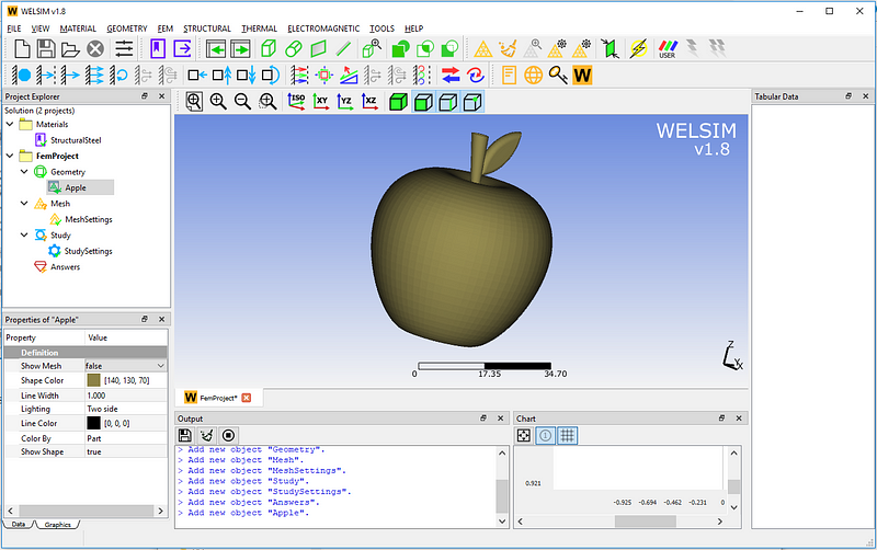
Since it is an STL geometry model, the triangle patch mesh is displayed by default, and the user can choose to remove the grid in the display property window.
The next step is to generate a finite element mesh, click the Mesh All button to create a finite element mesh.
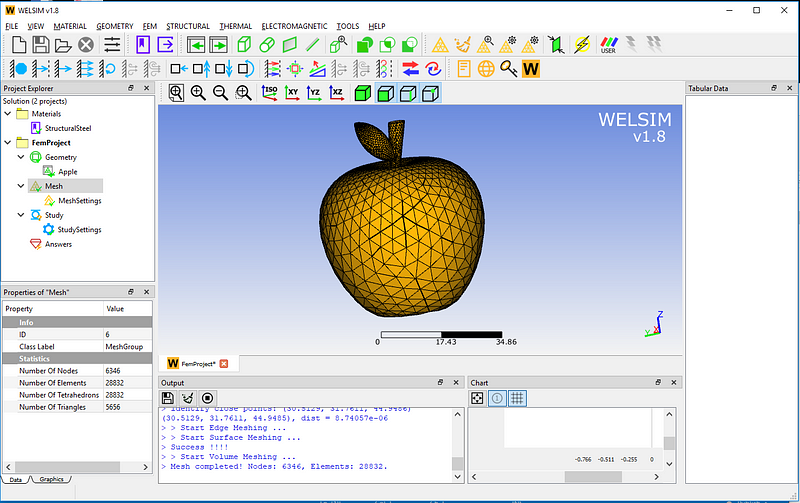
As shown, a total of 6346 nodes and 28832 Tet4 elements are generated.
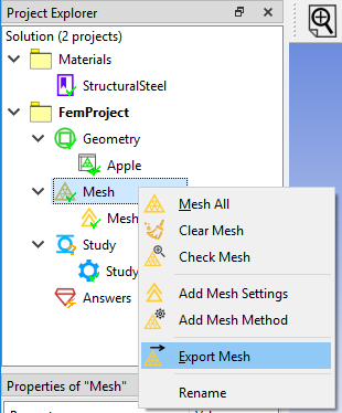
The user can save the generated limited unit data as a file. Right click on the Mesh node and select Export Mesh. As shown below
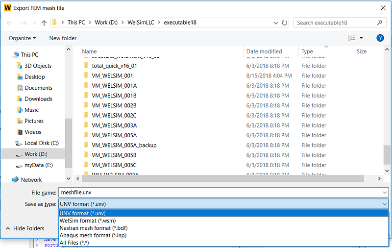
The currently supported grid file formats are UNV, WELSIM, Abaqus, and Nastran formats. The save dialog is as shown.
In the current version of WELSIM (v1.8), the meshing of STL geometry only supports Tet4 meshing, and the generated mesh does not support subsequent finite element analysis yet.
For questions and suggestions about the functionalities of WELSIM, please visit https://welsim.com.