The Hertz contact theory is a study of the local stress and strain distribution law when two objects contact with pressure. In 1881, H.R. Hertz first studied the elastic deformation of glass lenses by creating force through contacting them with each other. He assumes that:
1) Small deformation occurs in the contact area.
2) The contact surface is elliptical.
3) The object in contact can be regarded as an elastic semi-space, and only the distributed normal pressure acts on the contact surface.
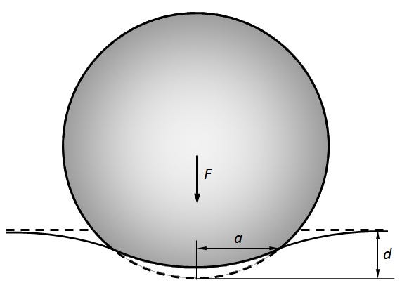
Any contact that satisfies the requirements above is called a Hertz contact. When the contact surface is approximately a quadratic paraboloid, and the size of the contact surface is much smaller than the object size and the curvature radius of the surface, the Hertz theory can give the results consistent with experimental results. In the Hertz contact problem, since the deformation near the contact area is strongly restrained by the surrounding area, the stress is highly concentrated. Additionally, the contact stress is nonlinear with the applied pressure and is determined by the elastic modulus and Poisson’s ratio of the material.
It’s clear there can be various types of structures related to Hertz contact. In this example, we only look at the cylinder-plate contact. The schematic diagram of the contact analysis is as follows.
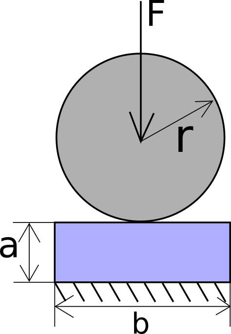
Where the given geometric parameters are: a = 4 mm, b = 16 mm, r = 8 mm, and the force is F = 100 N.
Now let’s take a look at how to conduct Hertz contact analysis in WELSIM.
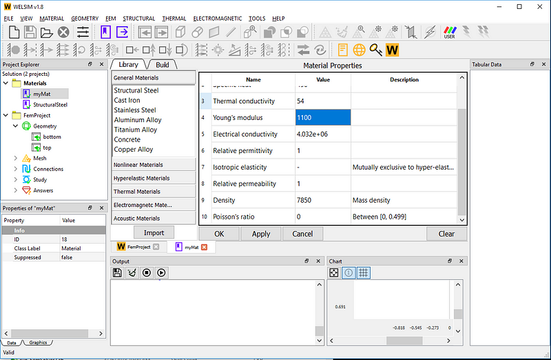
First set the material properties. Add a material object and name it “myMat”, set Young’s modulus and Poisson’s ratio to 1100 and 0.3, respectively.
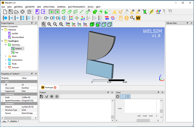
To simplify the analysis, a symmetric structure model is used. Geometry models can be built from a CAD tool and imported into WELSIM. The previously created myMat material is assigned to these two parts.
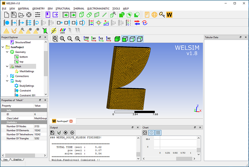
In the mesh settings, set the maximum element size to 0.3 and click the “Mesh” button. The generated mesh below has a total of 3153 nodes and 1042 Tet4 elements.
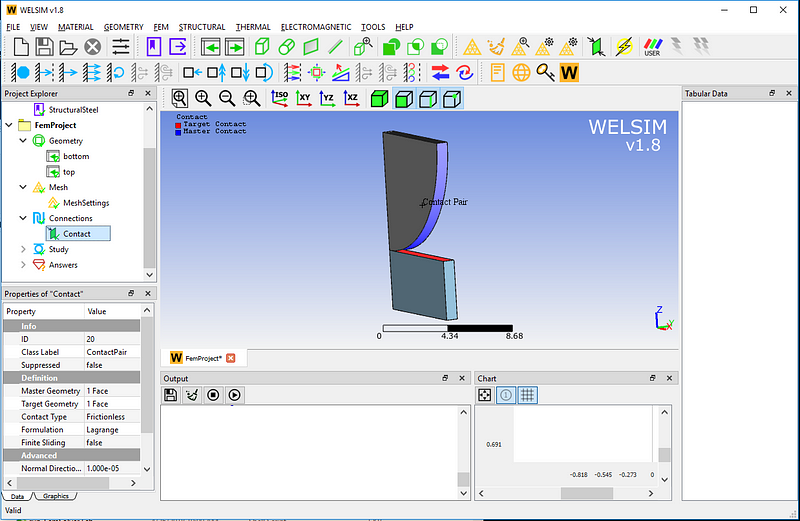
Set the contact pair. Scope surfaces of the cylinder and plate, and assign them to the contact pair. Set the Contact Type to Frictionless, and the other properties remain with the default values.
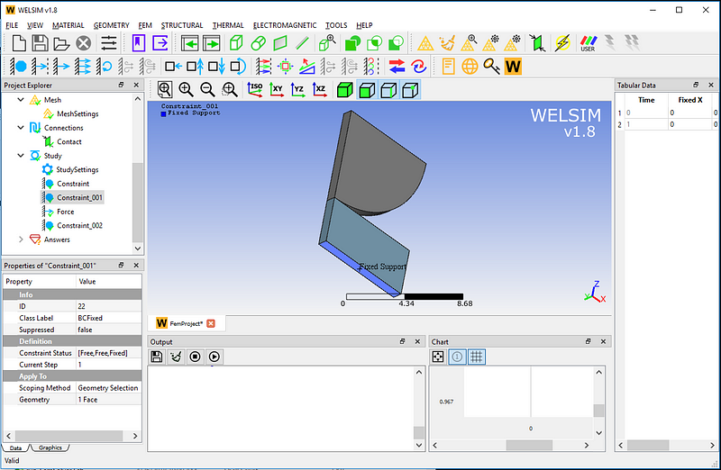
Set the boundary conditions, such as fixed supports and symmetric faces. (To keep this article short, we only show one fixed support boundary condition here. The example project file in the installation directory contains all the detailed settings.)
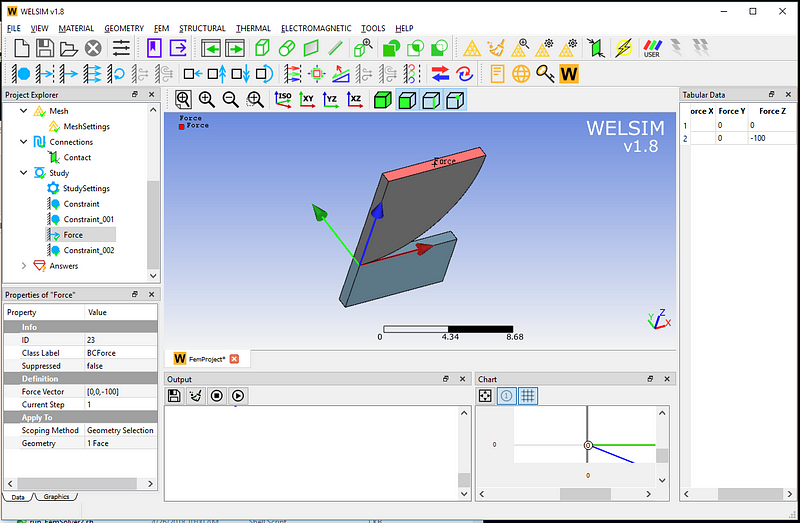
A downward force in the Z direction is applied to the upper end of the structure, which has the magnitude of 100.
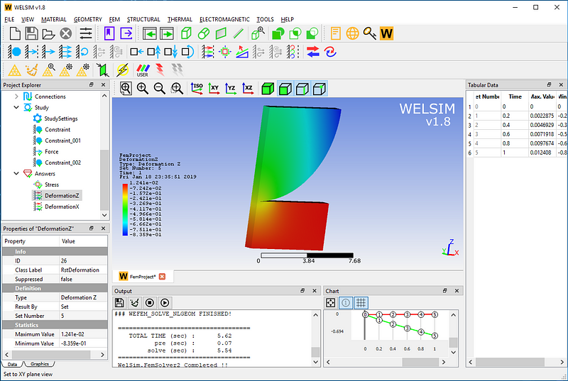
Click the Compute button, and quick results will appear. Add deformation and stress result objects, and then evaluate these results. Since five substeps are defined, there are five result sets.
The Z-direction deformation result contour is below.
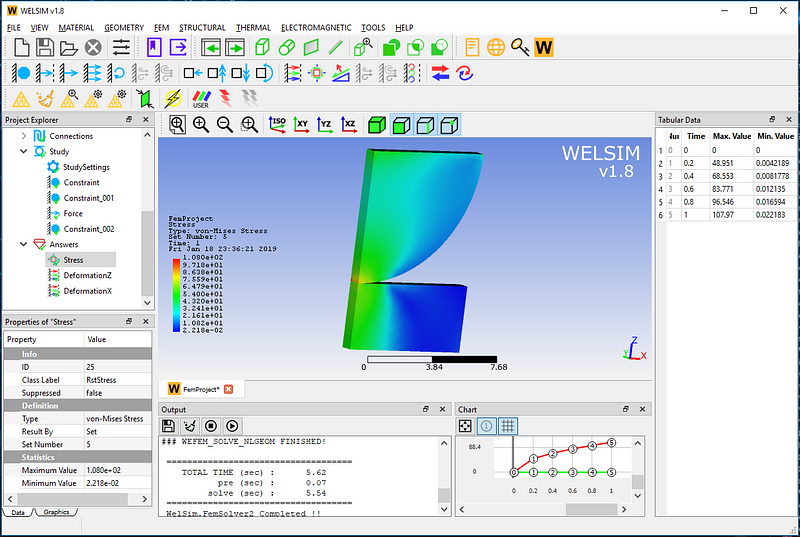
Underneath is the Von-Mises stress result contour.
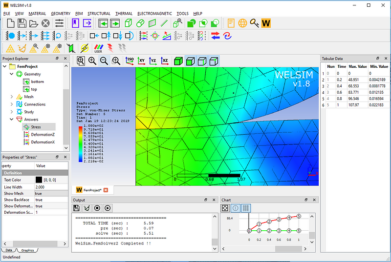
Turn on the deformation and mesh display, and zoom in onto the local view of the contact area. The user will be able to see the deformation of the structures, as well as the increased contact area.
This example is saved in examples/structural_contact/contact_Hertz_ex9.wsdb in the installation directory. If you have any questions about WELSIM’s contact analysis, please leave us a message or visit https://welsim.com.