Transient structural analysis is used to study the dynamic response of structures that are subjected to loads in the time domain. The transient analysis methods provided by WELSIM include implicit dynamics analysis, explicit dynamics analysis, and modal analysis. Now, let’s take a look at how to use the transient module to solve the linear dynamics problems.
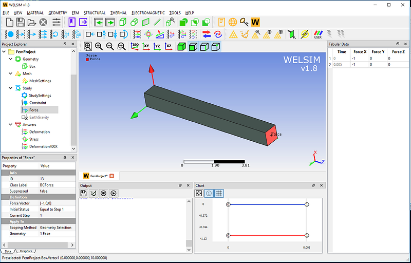
The model is as follows. A cantilever beam is fixed at one end, and a force load impacts the other end. The finite element analysis manages to reveal the dynamic response of the elastic body under this condition.
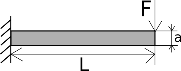
The dimensions of the structure, material properties, and loads are as follows: Length L = 10 mm Cross-sectional area side length a = 1 mm Young’s modulus E = 4000 kgf/mm2 Poisson’s ratio v=0.3 Mass density rho=1e-9 kg fs2/mm3 Gravity acceleration g= 9800 mm/s2 External force F0 = 1 kgf
Now, we perform linear dynamic analysis in WELSIM.
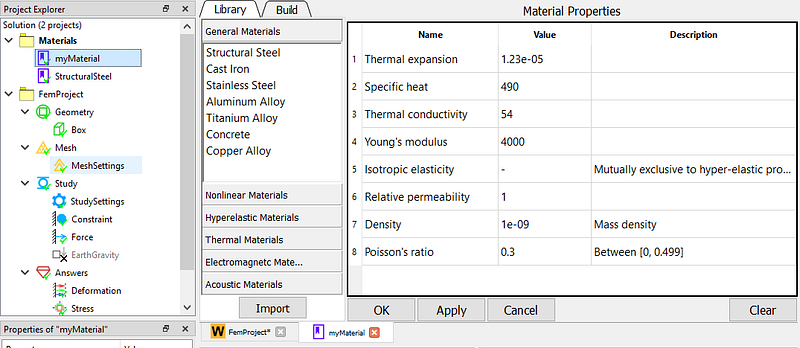
First set the material properties. Create a material object and rename it “myMaterial”, set Young’s modulus to 4000, the Poisson’s ratio to 0.3, and the mass density to 1e-9.
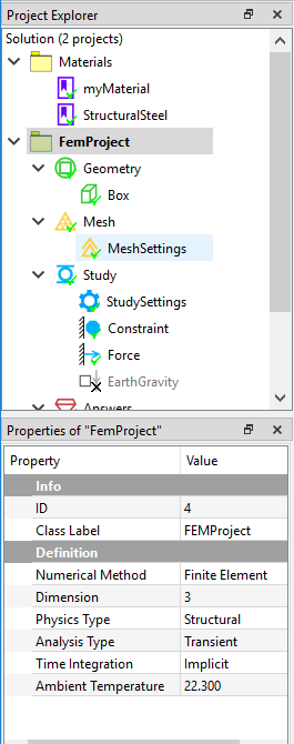
Define the analysis type. In the FEM project object, set the Analysis Type property to Transient and use the default Implicit time integration solver.
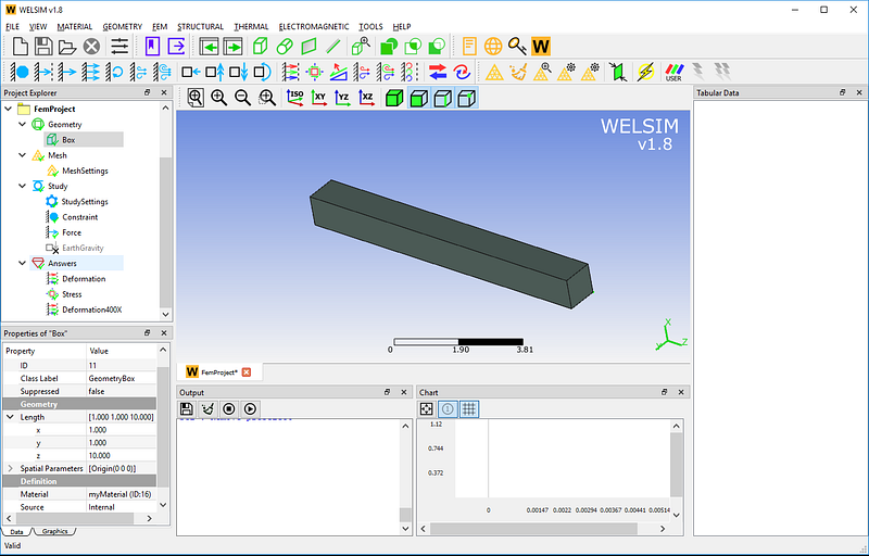
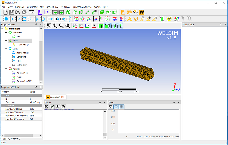
Create cantilever beam geometry. Due to the simple structure of the cantilever beam, users can create this shape using the WELSIM built-in CAD command. Click the Box geometry, and set the size to 1x1x10. Then assign the material “myMaterial” to this part.
In the mesh settings, the maximum element size is set to 0.3, and the quadratic element is applied. As shown in the figure below, a total of 4035 nodes and 2238 Tet10 elements are generated.
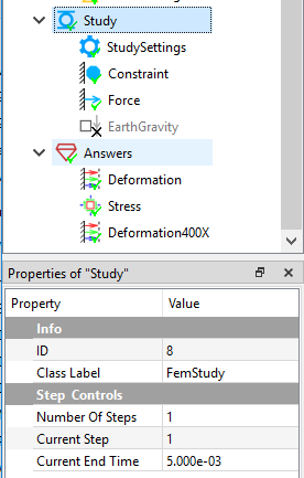
In the Study object, set the analysis end time to t1=5e-3.
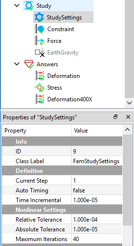
In the Study Settings object, set the time step to 1e-5.
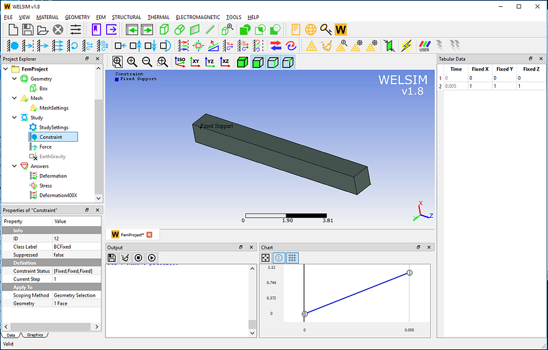
Define boundary conditions. Apply a fixed support to one end of the cantilever beam.
At the other end of the cantilever beam, impose a force along the X direction, with the magnitude of 1 kgf. The initial state is set to Equal to Step 1.
Click the Compute button, and you will get the results quickly. Add deformation and stress result objects and evaluate these results. There are five hundreds of result sets generated.
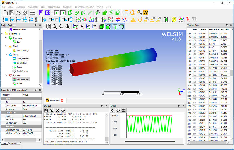
X-direction deformation result contour at time 0.002 seconds. The graph window in the lower right corner shows the fluctuation curve of the maximum displacement.
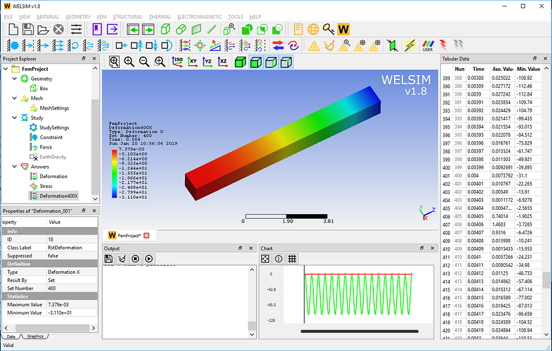
X-direction deformation result contour at time 0.004 seconds.
von-Mises stress result contour at time 0.004 seconds.
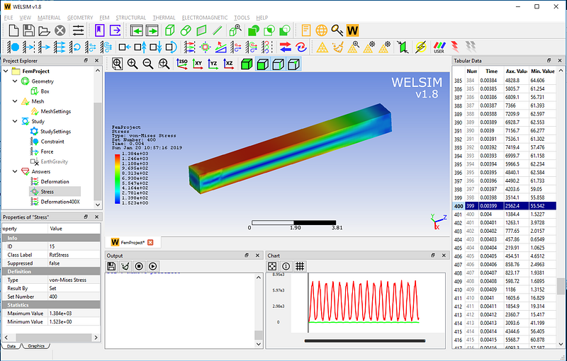
It can be seen that the cantilever beam under the impact of a constant load, due to the elastic properties, will produce up and down vibration. Both amplitude and frequency can be obtained quickly by this calculation. The implicit time solver is applied in this example, the explicit time solver is also available in WELSIM.
This example is saved in the installation directory of examples/v18/linear_dynamics_cantilever_beam.wsdb. If you have any questions about the linear dynamics analysis of WELSIM, please leave us a message or visit https://welsim.com.