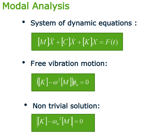
The goal of the modal analysis is to get the mode shape and natural frequency of a structure. The calculated stress, strain, and displacement values have no practical quantitative significance but can be used to understand the resonance region of the structure and guide structural design. The modal analysis plays a fundamental role in subsequent analyses, such as vibration characteristics, fault diagnosis, structural dynamics, and optimization.
Mathematically, the essence of modal analysis is to calculate the eigenvalues and eigenvectors of the governing equations. The number of modes is infinite. However, only the low-order modes are dominant for the structural motion, so we just need to calculate preliminary natural frequencies.
For a three-dimensional object with free motion, the first six modes are rigid body displacement modes with zero natural frequency; and for constrained objects, there is no rigid body mode. The correctness of the constraint has a significant impact on the modal analysis results. Therefore, we need to pay attention to impose the constraints on the structure and match the actual physical conditions.

The general-purpose finite element software WELSIM provides modal analysis features. With simple setup, the user can easily, quickly and accurately obtain the natural frequency and mode shape of the structures. Let’s take the turbine rotor as an example to see how to perform the modal analysis.
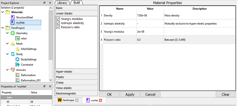
Start the WELSIM software application. First set the material properties. Add a material node and name it “myMat”, set Young’s modulus to 2e8 kg/(mm s2), Poisson’s ratio of 0.3, and mass density of 7.85e6 kg/mm3. It is essentially structural steel.
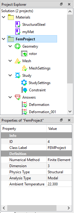
Set the analysis type. In the FEM project object, set the Analysis Type property to Modal.
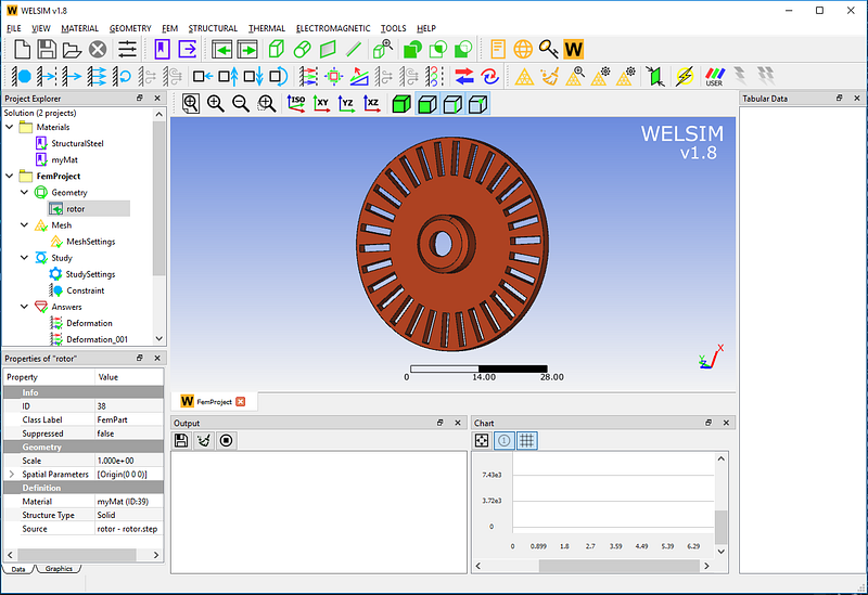
Create a rotor model by importing a STEP file. And assign the “myMat” to the material property, as the picture shows:
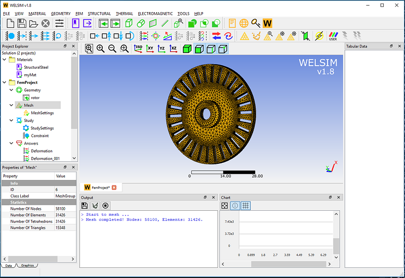
In the Mesh Settings, use a high-order (Quadratic) element and a high-density (Very Fine) grid. A total of 58,100 nodes and 31,426 Tet10 elements were generated.
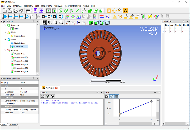
For a three-dimensional structure without constraints, the natural frequency of the first six orders is zero. To understand the natural frequency and mode shape of the rotor under actual conditions, impose a fixed support boundary condition at the center of the rotor. As the picture shows,
Click the Solve button. The system defaults to calculate the first six modes, so we add six result objects to view the resonant shape separately.
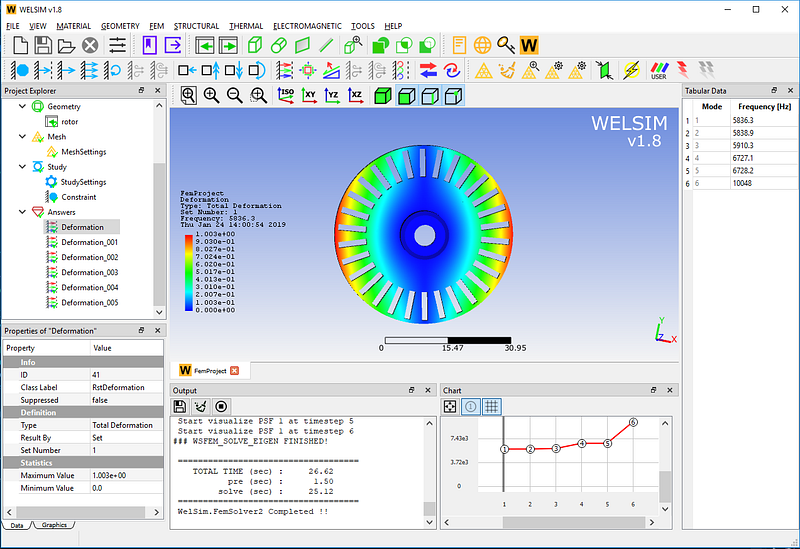
The first-order mode has a natural frequency of 5836.3 Hz.
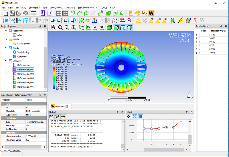
The second-order mode has a natural frequency of 5838.9 Hz.
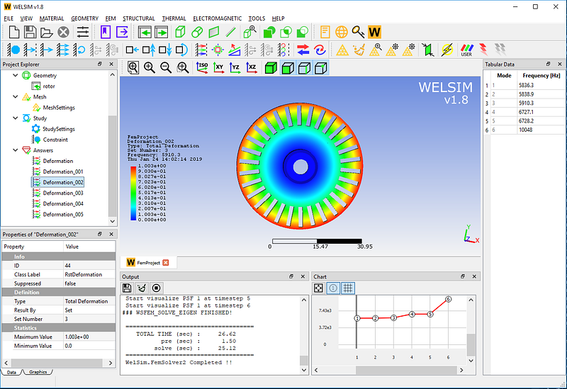
The third-order mode has a natural frequency of 5910.3 Hz.
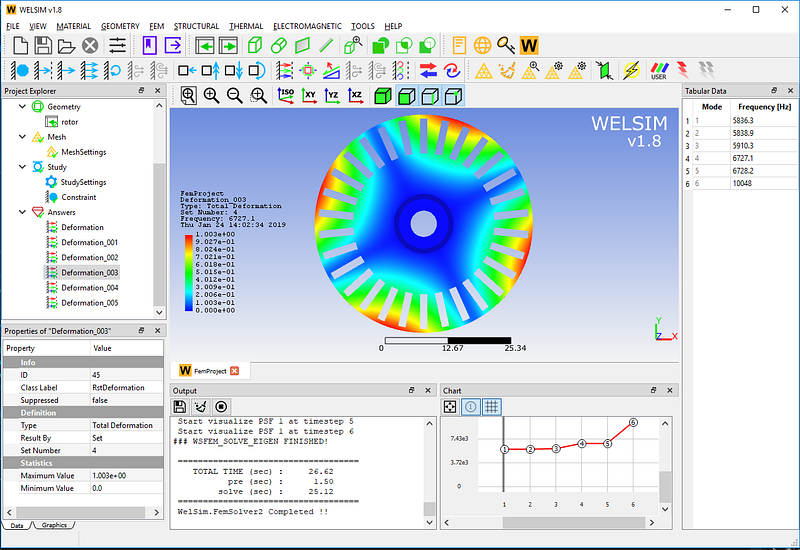
The fourth-order mode has a natural frequency of 6727.1 Hz.
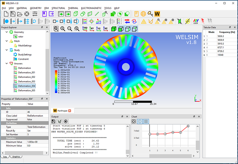
The fifth-order mode has a natural frequency of 6728.2 Hz.
The sixth-order mode has a natural frequency of 10048 Hz. Meanwhile, Display deformation and mesh.
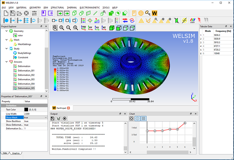
Note that the value of the deformation result here is not a real deformation, but a relative reference value. The table window on the right and the curve window at the bottom also list the specific natural frequency values.
This example is saved in examples/v18/modal/modal_turbine_rotor.wsdb in the installation directory. If you have any suggestions or comments about WELSIM’s modal analysis, please leave us a message or visit https://welsim.com.